Steps :-
1) First open the schematics window.
2) Click on “GET
NEW PART” and take the parts,
a) D1N4002 for diode
b) R for resistor
c) VDC for DC source
d) GND_EARTH for ground
3) Place the parts in suitable
location.
4) Wire the parts using “DRAW WIRE” in
the top.
5) When the circuit is completed, save
the file with a name.
6) Then click on “Electrical Rule
Check” under “Analysis” at top.
7) Then click on “Create Netlist”
under “Analysis” at top.
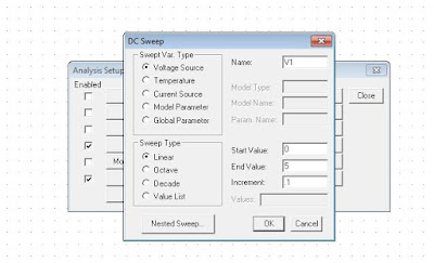
8) Then take “Setup” under the same “Analysis”
.
9) Give the needful values there.
10) Then take “Simulate” under the same
“Analysis” .
11) Then form output window at task-bar.
12) Open it, and select trace and axis
variables.


No comments:
Post a Comment