Steps :-
To download the video for the simulation , Click Here
1) First open the schematics window.
2) Click on “GET NEW PART” and take the parts,
a) D1N4002 for diode
b) R for resistor
c) VDC for DC source
d) GND_EARTH for ground
3) Place the parts in suitable location.
4) Wire the parts using “DRAW WIRE” in the top.
6) Then click on “Electrical Rule Check” under “Analysis” at top.
7) Then click on “Create Netlist” under “Analysis” at top.
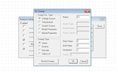
8) Then take “Setup” under the same “Analysis” .
9) Give the needful values there.
10) Then take “Simulate” under the same “Analysis” .
11) Then form output window at task-bar.
12) Open it, and select trace and axis variables.


No comments:
Post a Comment